How to detect the capacitor on the repair circuit board?
1. Detect electrolytic capacitor
The steps for measuring electrolytic capacitance with a pointer multimeter are as follows:
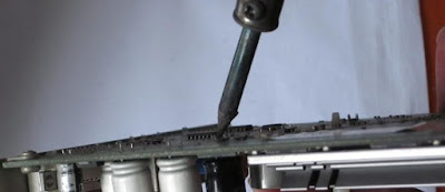
First, use an electric soldering iron to remove the electrolytic capacitor to be tested from the circuit board.
Second, observe whether the electrolytic capacitor under test has obvious problems such as cracks, broken pins, burnt black, and liquid leakage. If there is, it means that the capacitor has failed.
Third, wipe clean the pins of the electrolytic capacitor to be tested and discharge them with tweezers.
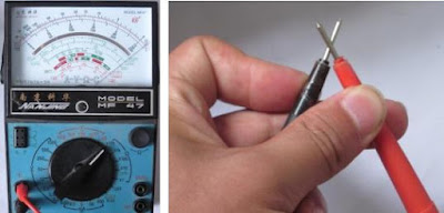
Fourth, select the "R*10" gear of the multimeter, and short-circuit the two test leads for zero-return calibration.
Short-circuit the two leads
Fifth, connect the red test lead of the multimeter to the negative pole of the capacitor and the black test lead to the positive pole of the capacitor and observe the pointer change.
(A) The pointer has a large deflection at the moment of contact.
(B) The pointer stays at infinity after being stationary.
After testing, when the test pen touches the two poles of the capacitor, the watch needle quickly deflects to the right, and then swings to the left to the end, indicating that the capacitor is basically normal; if the resistance value indicated by the watch hand is very small, the capacitor has broken down; if the needle has no deflection, it indicates The capacitor has an open circuit.
2. Detection of chip capacitors
The method of detecting chip capacitors with a digital multimeter is as follows:
Digital multimeters generally have jacks specially used to measure capacitance. Unfortunately, there is no suitable pair of pins that can be inserted into chip capacitors, so you can only use the ohm file of the multimeter to make a rough measurement. Even so, the measurement results are still convincing.
(1) First observe whether the capacitor has obvious physical damage. If there is, it means that the capacitor has been damaged. If not, further measurement is required.
(2) Wipe clean the two poles of the chip capacitor to be tested with a brush to prevent the dirt remaining on the two poles from affecting the measurement results.
(3) For the accuracy of the measurement, it is necessary to discharge the capacitor with tweezers.
(4) Select the secondary tube file of the digital multimeter, and insert the red test lead into the VΩ hole of the multimeter and the black test lead into the COM hole of the multimeter.
(5) Connect the red and black test leads to the two poles of the chip capacitor and observe the changes in the dial reading.
(6) Exchange the two test leads and test again, and pay attention to the changes in the readings on the dial.
The dial first has a flashing resistance value.
It reads 1 after resting.
The digital meter for the two measurements has a flashing value first, and then it becomes 1, that is, the resistance value is infinite, so the capacitor is basically normal. If the above method is used to detect, the multimeter always displays a fixed resistance value, indicating that the capacitor is leaking; if the multimeter always displays “000”, it indicates that the capacitor is short-circuited; if it always displays “1” (there is no flashing value, directly Is 1.), an open circuit has occurred between the internal poles of the capacitor.


Comments
Post a Comment
Tell us your opinion