ASIC Miner ICERIVER KAS KS0 Profitability In the realm of cryptocurrency mining, the Iceriver KAS KS0 miner has garnered widespread attention. Tailored specifically for the Kaspa network's KHeavyHash algorithm, it boasts high hashing power and low power consumption, making it an ideal choice for many miners. In this article, we will comprehensively assess IceRiver KS0 profitability while considering the Kaspa market conditions and the attributes of KS0 miner. Kaspa Market Dynamics Kaspa is a vibrant cryptocurrency network aimed at delivering high performance and scalability for everyday transactions. At the time of writing this article, the Kaspa coin trades at approximately $0.04959. But it's essential to note that cryptocurrency markets are highly susceptible to price volatility. Hence, investors must remain vigilant about market dynamics. Additionally, the Kaspa network's mining difficulty and reward mechanisms play a role in mining returns. Attributes of the IceRiver KS...
How to test the voltage and ground value of the power supply unit of the Antminer S9 hash board?
Antminer S9 hash board
Antminer S9 hash board power supply unit
Voltage and ground value test of Antminer S9 power supply unit
12V voltage test
Test method: adjust the Fluke 15B+ multimeter to the DC gear; the red test lead is placed on the positive pole of the power interface of the hash board, and the black test lead is placed on the negative pole of the power interface.
PIC chip voltage test
There is a white dot next to the PIC chip, which is 1st Pin.
Test method: Adjust the Fluke 15B+ multimeter to the DC gear, measure whether the 1st Pin of the PIC chip has output, and the normal voltage is about 3.3V. If there is no 3.3V, please check the connection status of the hash board test line to see if the hash board is normal; if not, you need to re-program the PIC.
MOS tube voltage test
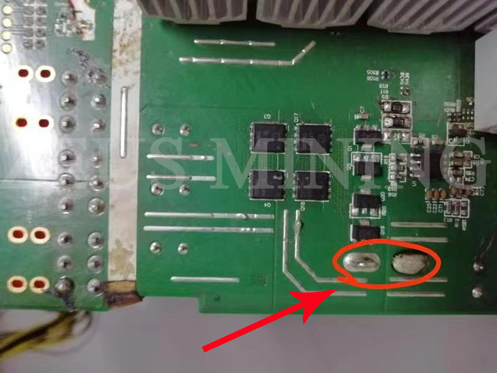
There is a black dot on the MOS tube, which is the 1st Pin (Figure 1). This is because the voltage of the MOS tube is the 1st Pin input and the 8th Pin output.
Test method: The Fluke 15B+ multimeter is adjusted to DC gear, the black test lead is placed on the heat sink, and the red test lead is placed on the 1st or 8th Pin of the MOS tube; the input and output values of the MOS tube voltage can be measured, normal There will be 9V input and output.
If the voltage is abnormal, it is necessary to measure the ground value of the MOS tube.
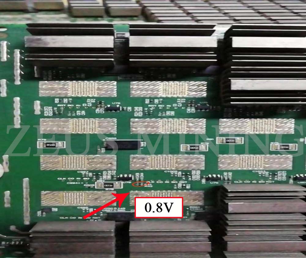
Ground value detection method: adjust the Fluke 15B+ multimeter to the diode gear position, place the red test lead on the heat sink, and place the black test lead on the 1st or 8th Pin of the MOS tube. If the ground value is abnormal, replace the MOS tube. (To judge whether the resistance of the MOS tube is abnormal, you can compare it with other MOS tubes). Alternatively, the voltage and ground values can also be detected through the two points in the red circle (Figure 2).
 |
Figure 1 |
 |
Figure 2 |
LDO 1.8V and PLL 0.8V output voltage test
There is a white dot next to LDO 1.8V, which is the 1st Pin. The LDO 1.8V voltage is the 1st Pin input and the 5th Pin output.
Test method: Fluke 15B + multimeter DC gear, the black test lead is placed on the heat sink of the same domain, the red test lead is placed on the 1st Pin, normally there will be 2.5V input, and the red test lead is placed on the 5th Pin, normally there will be 1.8V output. Some Antmner S9 versions can directly test the 1.8V test hole on the PCB.
The PLL 0.8V test point is on both sides of the voltage divider resistors R41 and R42.
Test method: Fluke 15B + multimeter DC gear, red and black test leads are placed on both ends of the voltage divider resistors R41 and R42, and there will be a normal output of 0.8V. Some Antmner S9 versions can directly test the 0.8V test hole on the PCB.
If the voltage is abnormal, it is necessary to measure the ground value of LDO 1.8V and PLL 0.8V.
Ground value detection method: same as above. If the ground value is abnormal, replace the corresponding LDO 1.8V and PLL 0.8V. (To judge whether the resistance of LDO 1.8V and PLL 0.8V is abnormal, you can compare other LDO 1.8V and PLL 0.8V)
14V voltage test
Through the two ends of the vacancy, 14V can be measured.
Test method: Fluke 15B + multimeter DC gear, the red test lead is placed on the positive pole of the power interface of the hash board, and the black lead is placed on the negative pole of the power interface.


Comments
Post a Comment
Tell us your opinion