ASIC Miner ICERIVER KAS KS0 Profitability In the realm of cryptocurrency mining, the Iceriver KAS KS0 miner has garnered widespread attention. Tailored specifically for the Kaspa network's KHeavyHash algorithm, it boasts high hashing power and low power consumption, making it an ideal choice for many miners. In this article, we will comprehensively assess IceRiver KS0 profitability while considering the Kaspa market conditions and the attributes of KS0 miner. Kaspa Market Dynamics Kaspa is a vibrant cryptocurrency network aimed at delivering high performance and scalability for everyday transactions. At the time of writing this article, the Kaspa coin trades at approximately $0.04959. But it's essential to note that cryptocurrency markets are highly susceptible to price volatility. Hence, investors must remain vigilant about market dynamics. Additionally, the Kaspa network's mining difficulty and reward mechanisms play a role in mining returns. Attributes of the IceRiver KS...
What are the common problems with Fluke digital multimeters?
Fluke multimeters are praised and loved by users for their accuracy, durability, safety, innovation, portability, and easy operation. Here ZEUS MINING explains to you the common problems and solutions we encountered in using the multimeter.
Question: Why doesn't my multimeter return to zero when it is turned on, there are always small digital changes?
Answer: There will be a certain reading on the dial before the user starts to use the multimeter in many cases. This is mainly due to the influence of the external electrical atmosphere, including the interference of the electromagnetic field and air static electricity. But when the red and black test leads are short-circuited to form a loop, and the multimeter reads 0 or close to 0. Because in the actual test, the multimeter is connected in parallel or series in the loop, and the red and black test leads are equivalently short-circuited by the tested loop, which can effectively avoid the interference of the external environment and ensure the accuracy of the test results.
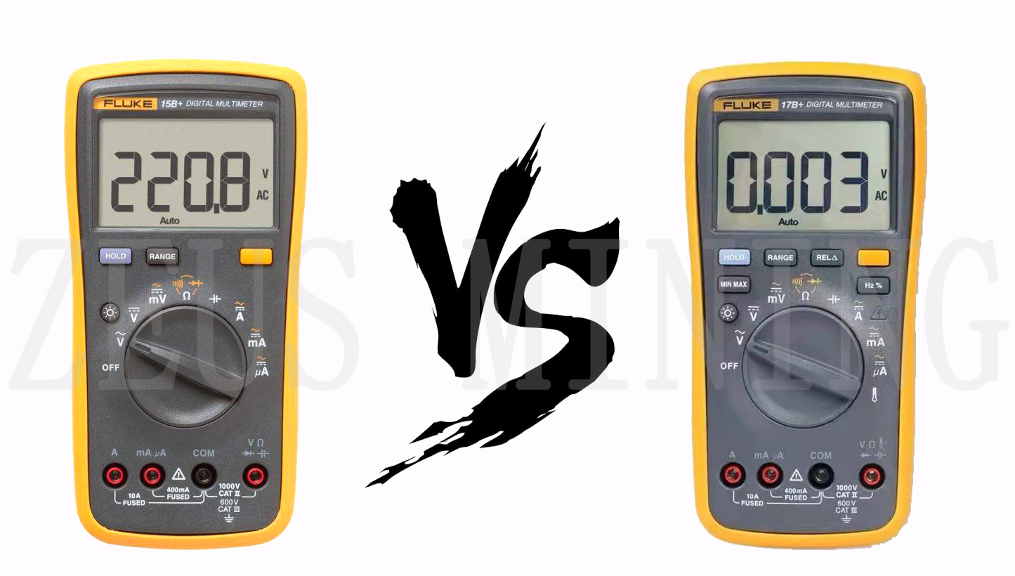
Question: What is the difference between 15B, 17B, and 15B+, 17B+?
Answer: 15B and 17B are currently discontinued. The corresponding upgrade replacement models are Fluke 15B+ and Fluke 17B+. Compared with the old model, the main upgrade content of the new model is: the screen is increased by 50%, the speed is faster, and the backlight function is added.
Question: Will the multimeter be damaged if I accidentally connect the wrong gear?
Answer: The current gear of the multimeter is protected by a fuse; the voltage gear can detect 1000V high voltage and has an internal resistance of 10MΩ, so it will not be burned; and the resistance gear is not protected the resistance gear is internally a voltage excitation source. The output voltage detects the resistance under test by detecting the current flowing through the resistance under test. Therefore, once the voltage is measured with the resistance gear, it will be hedged by two voltage sources, which may burn the resistance gear of the multimeter.
Question: What does the word count mean in the accuracy index (1% reading + 3 words)?
Answer: It refers to the least significant bit of the instrument under the range. For example, we use a 6000-word multimeter to measure 120V AC voltage (A/D converter from 0 to 5999 words). To measure 120V AC voltage, the meter must be in the 600.0 AC voltage range. Then the resolution (least significant bit) is 0.1V. (120V * 1% = 1.2V + 3 words) = (1.2V + 0.3V) = 1.5V.
Question: What is the difference between the Min/Max mode and the peak mode of the multimeter?
Answer: As the name implies, the "Min/Max" mode is the maximum and minimum readings measured by the multimeter from the start of the "Min/Max" recording mode. Generally, to obtain accurate readings, it is necessary to measure the maximum or minimum value of the signal within 200 to 350 milliseconds or longer. They are suitable for any mode, such as DC voltage, AC voltage true RMS, resistance, and current functions. The "Peak" mode measures the signal's positive and negative peak voltages. For example, for a 120V AC line, the peak reading will reach +169V and -169V (for a pure sine wave, 120V * 1.414 = 169V). In general, they work well for 250 microseconds or more extended peaks.
Question: Why is the meter reading not zero when the test line is short-circuited in resistance mode?
Answer: The meter measures the resistance of the test leads. The resistance range of a new set of test leads is usually 0.1 to 0.3Ω. Therefore, the test lead error needs to be subtracted from the resistance reading. Some more feature-rich meters will provide a "Relative delta" (relative delta) (the actual Δ symbol in the final result) mode button, which will subtract the test line error.
Fluke15B+, 17B+ features and technical specifications comparison
Remarks: Y represents this range or has this function, N represents not this range or includes this function.
AC voltage V is suitable for 40Hz-500Hz, and AC current A is suitable for 40Hz-400Hz.


Comments
Post a Comment
Tell us your opinion