ASIC Miner ICERIVER KAS KS0 Profitability In the realm of cryptocurrency mining, the Iceriver KAS KS0 miner has garnered widespread attention. Tailored specifically for the Kaspa network's KHeavyHash algorithm, it boasts high hashing power and low power consumption, making it an ideal choice for many miners. In this article, we will comprehensively assess IceRiver KS0 profitability while considering the Kaspa market conditions and the attributes of KS0 miner. Kaspa Market Dynamics Kaspa is a vibrant cryptocurrency network aimed at delivering high performance and scalability for everyday transactions. At the time of writing this article, the Kaspa coin trades at approximately $0.04959. But it's essential to note that cryptocurrency markets are highly susceptible to price volatility. Hence, investors must remain vigilant about market dynamics. Additionally, the Kaspa network's mining difficulty and reward mechanisms play a role in mining returns. Attributes of the IceRiver KS...
How to choose a suitable fan simulator for the miner?
There are many types of fan speed simulators; how to choose? What is the functional difference? This article will help customers fully understand its functions and features through the fan speed simulator selection guide.
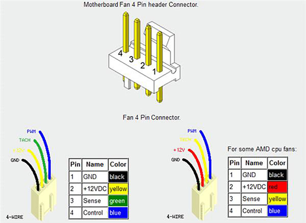
1. Definition of the fan interface:
All cooling fans (including CPU, GPU, miners) are defined according to the PWM standard interface, namely black cable (GND, ground cable, usually connected to negative pole), red cable (VCC, positive pole), 12V), yellow cable (SENSE, signal, speed cable), the blue cable (CTRL, control cable).
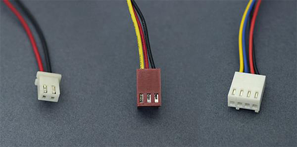
Actually, they have 3 kinds of cables:
Two-cable fan (black, red): there is no speed measurement function, and the speed can only be achieved by controlling the voltage and is generally used for heat dissipation of miner chassis fans.
Three-cable fan (black, red, yellow): Add a speed measuring cable, which can detect the fan's speed but cannot realize the speed. It is generally used for miner chassis fans' heat dissipation and early motherboard CPU heat dissipation.
Four-cable fan (black, red, yellow, blue): increase the control cable, which can realize speed regulation through the PWM signal. The new CPU fan, GPU, and miner fan use this interface.
Although miner fans all use four-cable fans, the shapes are also different:
2. Fan simulator
The fan simulator's purpose is to mute and reduce noise and use other low-noise equipment to dissipate heat, such as water cooling, air cooling, etc.
However, miners still need to detect whether there is a fan on the original fan interface, and most miners need a speed PWM signal to start. Therefore, when designing the fan speed simulator, the start signal and speed must be guaranteed to allow the miners to operate normally.
The fan speed simulator is more durable than ordinary speed fans (there is no loss, and no damage is seen in the middle), and the power consumption is relatively low.
Types of fan simulators: fixed speed and full speed
Fixed speed model (also called the three-cable model): Through the above knowledge, the three-cable simulator can only achieve constant speed (lack of control cable), which is generally fixed at 5000-6000 rpm. The implementation method is simple, the cost is cheap, there is no need to detect the PWM signal cable, and one-to-two can be realized by working in parallel (that is, one simulator is used to connect multiple fan interfaces, which are connected in parallel).
The disadvantage is that the miners are all designed with four cables, and the fixed speed model is only connected to three cables. In addition, some miners cannot detect the PWM control cable, so it will not work; that is, the compatibility and stability are not good.
The disadvantage is that the miners are all designed with four cables, and the fixed speed model is only connected to three cables. In addition, some miners cannot detect the PWM control cable, so it will not work; that is, the compatibility and stability are not good.
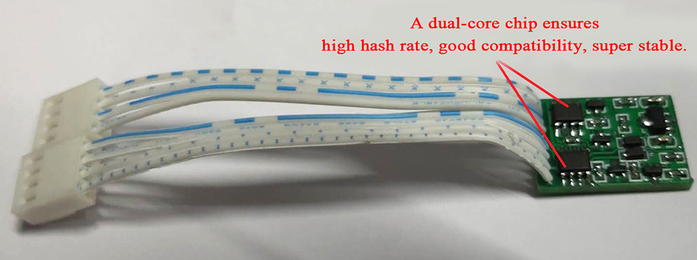
Full-speed model (also known as a four-cable model): full-speed is to completely simulate the working conditions of the fan and achieve a fully simulated speed of 2000-6500 rpm. For example, when a miner starts, it needs to start at high speed, then work at a low speed, and continuously adjust according to the working temperature of the miner fan speed. The full-speed simulator can fully realize all working conditions, and the stability and compatibility are pretty good. As long as the interface shape corresponds, there is no situation where it cannot be started. And for some miners, the hash rate is higher and more stable using the full-speed emulator.
The disadvantage is that the full-speed model has one control cable, which adjusts the speed according to the PWM signal sent by the miner. The control cables cannot work in parallel, so the one-to-two method cannot be implemented to save costs, but two-speed simulators are used to compare with the one-for-two method; the cost is only a few dollars less, and the stability and compatibility are far less worrying than these few dollars. It is strongly recommended that users choose full-speed simulators in direct-plug full-speed models, dual-core full-speed models, and other product options.
The disadvantage is that the full-speed model has one control cable, which adjusts the speed according to the PWM signal sent by the miner. The control cables cannot work in parallel, so the one-to-two method cannot be implemented to save costs, but two-speed simulators are used to compare with the one-for-two method; the cost is only a few dollars less, and the stability and compatibility are far less worrying than these few dollars. It is strongly recommended that users choose full-speed simulators in direct-plug full-speed models, dual-core full-speed models, and other product options.
3. What is one-to-two? How can we implement one-to-two? What is dual-core? What are the advantages and disadvantages of each? How to tell them apart?
Through the above knowledge, miners use four-cable interface fans, namely: GND (ground or negative), VCC (positive), SENSE (speed measurement signal), and CTRL (control signal). Everyone knows the power supply can be connected in parallel, not affecting the miners. SENSE speed measurement signal, CTRL (control signal), is detected and controlled through the I/O pins allocated by the CPU of the main control board. If two-speed measuring signal pins are connected in parallel for detection, it will not have a significant impact if the signals are relatively consistent. But CTRL (control signal) is controlled by the high and low levels sent by the CPU. It will conflict if one fan interface is high and the other is low. If the situation is serious, I/O pins will be burned, the CPU will be damaged, or it will stop working. Therefore, CTRL (control signal) is not allowed in parallel mode. That is to say, the fixed-speed three-cable can achieve one-to-two, and the full-speed four-cable can only be achieved by one-on-one mode. The full-speed dual-core implementation uses two independent chips to simulate, which is more expensive.
How to tell them apart:
The three-cable speed simulators (simulators) are all fixed-speed, and some are adjustable. A variable resistor is added to adjust the speed manually, and the speed is also fixed. Therefore, it is best to check the miners' backstage speed, generally starting at about 6000 rpm, and then adjust the fan speed according to the temperature (2000-6000 rpm, etc.).
Some customers reported buying a speed simulator and burning the miner's control board. In fact, the reason is straightforward: many manufacturers welded by hand themselves, without the equipment and workforce for batch testing, and only wanted to sell to make money. Therefore, it is shipped without testing. It is easy to burn the control board if the VCC pin is short-circuited with the SENSE pin or the GND pin. Therefore, buyers must buy from powerful manufacturers. Don't take risks because of the price difference; lose the big because of the small.
Solemnly declare: All fan speed simulators produced by ZEUS MINING have been thoroughly tested before delivery. Therefore, choosing us to buy is a guarantee of quality and a guarantee of confidence!
Solemnly declare: All fan speed simulators produced by ZEUS MINING have been thoroughly tested before delivery. Therefore, choosing us to buy is a guarantee of quality and a guarantee of confidence!


Comments
Post a Comment
Tell us your opinion