ASIC Miner ICERIVER KAS KS0 Profitability In the realm of cryptocurrency mining, the Iceriver KAS KS0 miner has garnered widespread attention. Tailored specifically for the Kaspa network's KHeavyHash algorithm, it boasts high hashing power and low power consumption, making it an ideal choice for many miners. In this article, we will comprehensively assess IceRiver KS0 profitability while considering the Kaspa market conditions and the attributes of KS0 miner. Kaspa Market Dynamics Kaspa is a vibrant cryptocurrency network aimed at delivering high performance and scalability for everyday transactions. At the time of writing this article, the Kaspa coin trades at approximately $0.04959. But it's essential to note that cryptocurrency markets are highly susceptible to price volatility. Hence, investors must remain vigilant about market dynamics. Additionally, the Kaspa network's mining difficulty and reward mechanisms play a role in mining returns. Attributes of the IceRiver KS...
How to use Aladdin Innosilicon series miner test fixtures?
I. Aladdin Innosilicon series miner test fixtures function description
Aladdin Innosilicon series test fixtures can test hash boards and digital power supplies independently of the computer. The test fixture supports Innosilicon T1, T2TS, T2TH, T2TZ, Aladdin L1, L2HF, L2HU, L2SU, L2HL, and other models. The power supply test supports all series of digital power supplies of Innosilicon.
The test fixture can accurately determine whether the miner's hash board and power supply are faulty without removing the shelf or dismantling the miner. The maintenance mode can accurately locate the cause of the hash board failure, significantly improving the miner's heat maintenance and operation and maintenance efficiency.
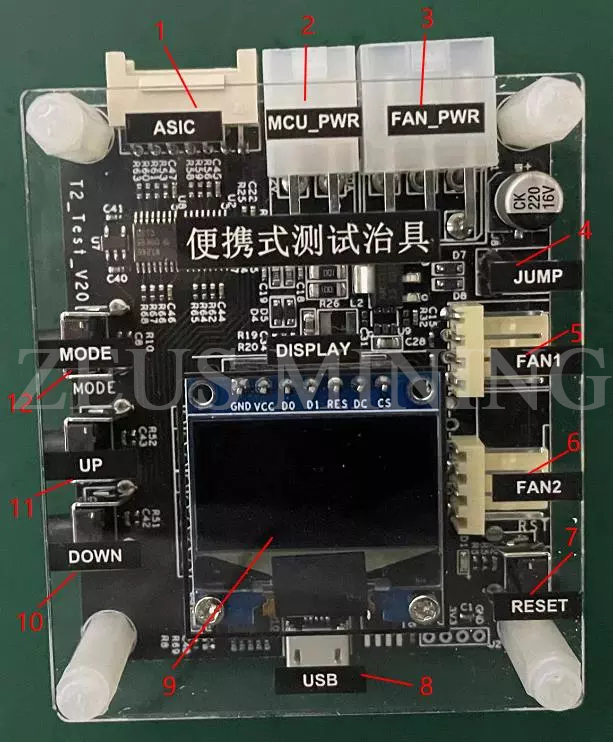
II. Interface description of Aladdin Innosilicon series test fixtures
1. Hash board interface;
2.4Pin power supply and power communication interface;
3.6Pin fan power supply interface;
4. Mainboard spare power jumper (when testing T1/L1, the test fixture needs to supply power from the fan power supply interface first and then short the jumper; otherwise, it can be kept disconnected);
5. 1 4Pin fan drive interface;
6. 2 4/6Pin fan drive ports;
7. Test fixture reset button;
8. USB communication interface (connect PC serial port at 115200 baud rate, can output detailed test information);
9. Brief test information display screen;
10. Up function button;
11. Down function button;
12. Debug mode function button;
III. Instructions for the use of Aladdin Innosilicon series test fixtures
1. Power supply test
1) Power supply quick test
When testing the digital power supply, insert the 4Pin power cable of the digital power supply into interface 2 of the test fixture, and then turn on the digital power switch to be tested. After waiting for about 8 seconds, you can observe the power supply test information through the test fixture display screen to judge whether the power supply to be tested is normal.
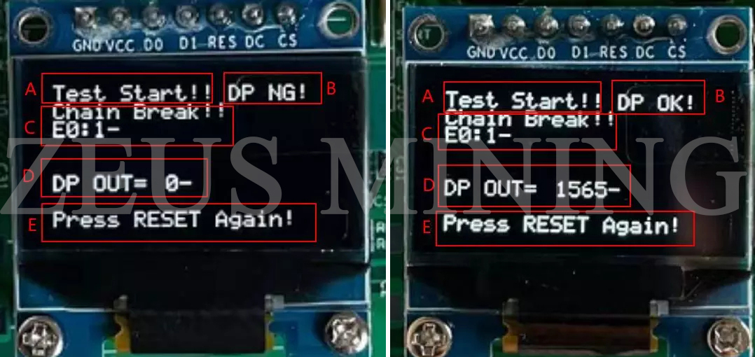
Display area content description:
A. "Test Start!!" prompts the test to start;
B. The power communication test has two results, "DP NG!" and "DP OK!";
C. "Chain Break!! E0:1-" shows the hash board test results. When measuring power supply, it can be ignored;
D. "DP OUT= 0-" "DP OUT= 1565-" indicates the output power voltage value. Represent output voltage 0V and output voltage 15.65V respectively;
E. "Press RESET Again!" indicates that the test has ended. Please press the reset button 7 of the test fixture to repeat the test.
2) Power supply depth test
Under normal circumstances, the test fixture will not enter the power supply full process test mode. Only when the UP (11 key) and DOWN (10 key) buttons are pressed and turned on before the power is turned on, the test fixture will enter the power depth test mode. After entering this mode, the MODE key can control the power supply's output voltage, and the 0~31 gear voltage can be manually adjusted through the UP and DOWN buttons.
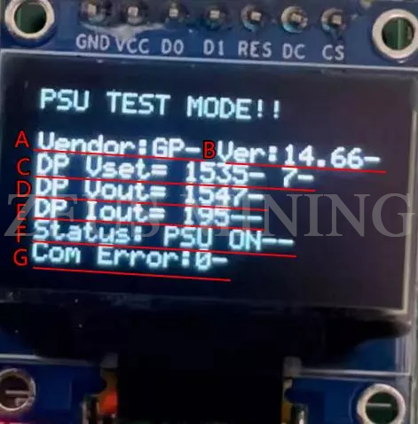
Display area content description:
A: "Vendor: GP-" indicates the power supply number;
B: "Ver:14.66-" indicates that the firmware version information of the power supply is 14.66;
C: "DP Vset= 1535- 7-" means that the power supply outputs 15.35V in the 7th gear state;
D: "DP Vout= 1547-" indicates that the power supply outputs a voltage of 15.47V;
E: "DP Iout=195--" indicates that the actual output current of the current power supply is 1.95A;
F: "Status: PSU ON--" means that the current power supply is in the output state, ON means open, OFF means close;
G: "Com Error: 0-" indicates the number of errors in power data communication. If it is not 0, there is a communication failure in the power supply, and the control board does not control the power supply.
2. Hash board test
1) Quick connection test
In this test state, the heat dissipation of the hash board is not so significant, and there is no need to connect the fan power cable and cooling fan.
When the USB serial port is not connected, you can view the test results on display. After the USB serial port is connected, find the correct COM port and open the serial port with a baud rate of 115200 to view the test details.
Display area content description:
A."Chain OK!" means that the hash board is connected successfully.
B. "Chips: 140-" indicates the number of chips on the hash board, 140.
C. "Vol Read OK! 454-" means the hash board chip voltage read successfully. And the average voltage of each chip is 454mV.
"TEMP Read OK! 16-" indicates that the hash board chip temperature is read successfully. And the average temperature of each chip is 16 ℃.
D. "Test PASS!" means the hash board test passed.
2) Full process test
In addition to the mining test, the hash board will generate a lot of heat in this test mode, and the fan power cable and cooling fan must be connected to achieve a good cooling effect.
Under normal circumstances, it will not enter the whole process test mode; only the test fixture is connected to the computer through USB; press and hold the debug mode function key 12 before powering on, and release the following content after the serial port prints the prompt information.
"----Enter Debug Mode!----"
"Please enter the PowerOn VID value (0~31, default 0):"
LED display shows "DEBUG MODE:"
Indicates that the whole process test mode is entered at this time. (Before entering this mode, please ensure that the power board interface of the test fixture is connected to the hash board to be tested, and the fan power supply and fan drive port are connected, and then power on for testing)
The specific setting steps are as follows:
Step 1: "Enter PowerOn VID value:"
According to the prompt, use the keyboard to set the power supply's output voltage during the test (between 0 and 31, the default is 0), which is the startup voltage of the hash board. The smaller the input value, the higher the output voltage (12V~16V).
Step 2: "Enter how often the hash board will run:"
Use the keyboard to set the running frequency of the hash board during the test (120~1400, default 0) according to the prompts. After entering the value, press Enter to confirm; the power consumption will be larger if the input value is larger.
Step3: "Press Enter to set pll!"
The voltage and temperature information read from the hash board will be displayed before increasing the operating frequency. Press Enter to confirm the frequency increase. If the Hash board chain fails, it will enter the maintenance mode and send maintenance instructions to the hash board without interruption. The power supply will not be interrupted, and an oscilloscope will be used to locate the faulty chip.
Step 4: "Press Enter to change the video!"
After increasing the operating frequency of the hash board to the specified value, if the above prompt appears, the power supply's output voltage can be automatically changed 5 times, and the voltage change of the hash board chip can be observed for each change.
Step 5: After the test, observe the expected output of the test results.
The content of this article is from the Internet, compiled and edited by ZEUS MINING. If there is any infringement, please get in touch with us to delete it.


Comments
Post a Comment
Tell us your opinion