ASIC Miner ICERIVER KAS KS0 Profitability In the realm of cryptocurrency mining, the Iceriver KAS KS0 miner has garnered widespread attention. Tailored specifically for the Kaspa network's KHeavyHash algorithm, it boasts high hashing power and low power consumption, making it an ideal choice for many miners. In this article, we will comprehensively assess IceRiver KS0 profitability while considering the Kaspa market conditions and the attributes of KS0 miner. Kaspa Market Dynamics Kaspa is a vibrant cryptocurrency network aimed at delivering high performance and scalability for everyday transactions. At the time of writing this article, the Kaspa coin trades at approximately $0.04959. But it's essential to note that cryptocurrency markets are highly susceptible to price volatility. Hence, investors must remain vigilant about market dynamics. Additionally, the Kaspa network's mining difficulty and reward mechanisms play a role in mining returns. Attributes of the IceRiver KS...
Antminer S17+ kernel log common fault and solution
The following log faults are from the backstage kernel logs of Antminer S17+ miners, and other Antminer models are for reference only.
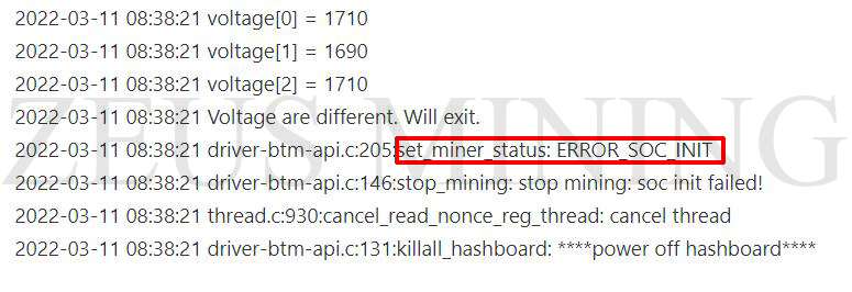
Fault 1: Hash board with inconsistent code mixed in
Solution:
Use the Antminer hash board code editor to synchronize the code of the hash board.
Working principle: Read the data of one of the normal hash boards through the hash board code editor and save it, and then write the normal hash board data to the hash board with inconsistent codes to make the serial numbers of the three hash boards consistent, so that the miner can work properly.
Click to learn more: How to use hash board code editor?
Fault 2: find 0 asic
Solution:
1. First, eliminate the problem of the data cable and the control board, and exchange the data cable of the hash board that displays "find 0 asic" with the data cables of the other two normal hash boards (only the hash board is replaced), to find the source of the fault.
2. Use the fluke17B+ multimeter to check whether the total voltage domain of the hash board is normal. If it is abnormal, you need to check whether the voltage of each PIC, MOS tube, and boost circuit is abnormal.
3. Check whether the RI signal voltage is normal. Find a group of RI signals on the chip on the edge of the domain from the middle domain for detection. If it is normal, we will check it forward, and if it is abnormal, check it backward.
Note: The transmission direction of the RI signal is from the last chip to the first chip.
4. If the kernel log and fixture detection show "ASIC=0 or NO hash board", it is necessary to check whether the voltage and ground value of the chip RI signal is abnormal. Suppose there is any abnormality, manually solder two times to eliminate the chip pseudo soldering failure. If it cannot be solved, replace the fault BM1397 chip.
RI signal to ground value test method: adjust the fluke17B+ multimeter to the diode gear position, place the red test lead on the heat sink in the same domain, and test with the black test lead. Whether the ground value is abnormal can be compared with the resistance value of other chips in the same domain.
For details, please refer to the Antminer S17+ hash board test shows "lack of ASIC chips" or "ASIC = 0"
Fault 3: temperature sensor chip fault
Solution:
According to the log, the first test is whether the voltage and resistance of No.51 and No.54 ASIC chips and their corresponding temperature sensor chips are abnormal. If the voltage and resistance values are normal, check whether the domain voltage and the 1.8V and 0.8V voltage of the same domain are normal.
Test method: Use the DC gear and diode gear of the fluke17B+ multimeter, connect the red test lead to the corresponding heat sink, and test with the black test lead. Whether the measured data is abnormal, the resistance value of other chips in the same domain can be compared.


Comments
Post a Comment
Tell us your opinion