ASIC Miner ICERIVER KAS KS0 Profitability In the realm of cryptocurrency mining, the Iceriver KAS KS0 miner has garnered widespread attention. Tailored specifically for the Kaspa network's KHeavyHash algorithm, it boasts high hashing power and low power consumption, making it an ideal choice for many miners. In this article, we will comprehensively assess IceRiver KS0 profitability while considering the Kaspa market conditions and the attributes of KS0 miner. Kaspa Market Dynamics Kaspa is a vibrant cryptocurrency network aimed at delivering high performance and scalability for everyday transactions. At the time of writing this article, the Kaspa coin trades at approximately $0.04959. But it's essential to note that cryptocurrency markets are highly susceptible to price volatility. Hence, investors must remain vigilant about market dynamics. Additionally, the Kaspa network's mining difficulty and reward mechanisms play a role in mining returns. Attributes of the IceRiver KS...
Antminer power supply fault location and repair method
How to locate the power supply failure of the miner? Here are three methods for detecting faults, and you can check them one by one according to the operation instructions!
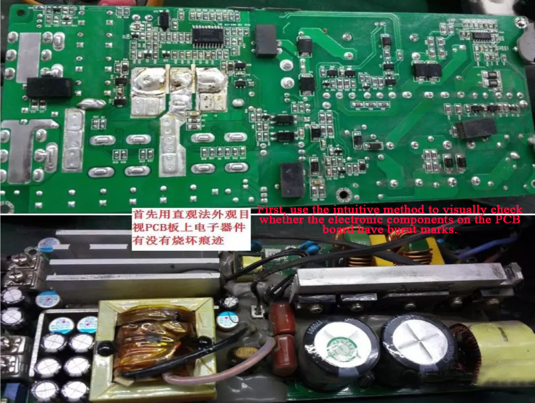
Intuitive method
1) Before repairing the faulty power supply, first use the voltage measurement method to power on to determine whether the power supply has voltage output (one is no voltage output, and the other is that the fan does not rotate with voltage output).
2) Test that the fan with voltage output does not rotate, and use a multimeter to measure the fan port. If the voltage is 12V, the output voltage is standard; you can directly replace the fan of the same type and then assemble the shell with screws to make a suitable power supply.
3) In the case of testing no voltage output, open the case and loosen the screws to take out the power supply PCB board. First, use an intuitive method to visually check whether the components on the PCB board are burnt out.
Resistance method
Visually, there are no burning marks on the components on the PCB board. First, use a multimeter to check whether each power component has a breakdown and short circuit, such as power supply rectifier bridge stacks, switch tubes, high-frequency high-power rectifier tubes, and whether the high-power resistors suppress inrush current are burned. Then check whether the voltage resistance value of each output port is abnormal. If it is abnormal, it is recommended to replace it directly:
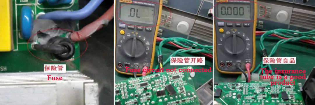
1) The fuse detection is measured with the short-circuit gear, and the resistance value is displayed as 0, indicating a good product. Otherwise, it is judged as an open circuit.
2) MOS tube, rectifier bridge stack, and common triode are measured with diode gears. The resistance value is displayed as 0.3~0.6, indicating good products. Otherwise, it is judged as poor breakdown and short circuit.
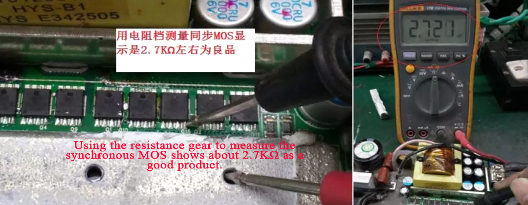
3) The synchronous rectification MOS tube is measured with the resistance gear, and the resistance value is displayed as about 2.7KΩ, indicating a good product. Otherwise, it is judged as a poor breakdown short circuit.
a. The resistance value of the synchronous rectifier MOS tube is measured to be about 2.7KΩ.
b. Measure the resistance of the synchronous rectifier MOS tube to be around 9~11Ω, and judge it as a breakdown failure (a group of synchronous rectification MOS shows a small resistance value as a failure product).
Voltage measurement
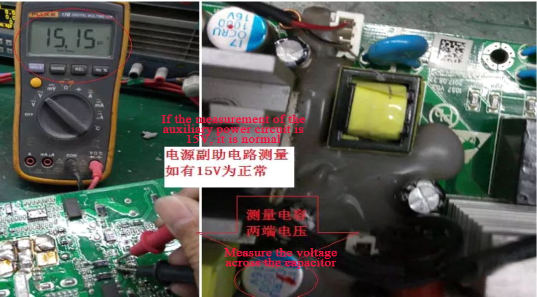
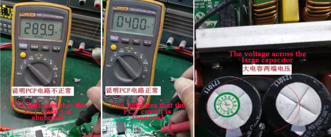
After the first step is completed, it still can't normally work after turning on the power, so detecting the PFC and PWM loops is necessary. Consult the relevant materials to become familiar with each function of the PFC and PWM modules and the prerequisites for the proper functioning of the modules. First, use the voltage measurement method to check whether the output voltage of the power supply auxiliary circuit is normal. Then, for the power supply with a PFC circuit, measure whether the voltage across the filter capacitor is about 300VDC. If there is no voltage of about 400VDC, the PFC module is not working correctly.
Power auxiliary circuit.
1) Detect the power factor module (PFC); if the voltage across the large capacitor is not about 400V, use a multimeter to detect the resistance of the PFC control chip and find that it is abnormal, and directly replace the PFC control chip.
When the voltage of the filter capacitor is about 400VDC, it means that the PFC circuit is working normally, and then it is necessary to check whether the output has a 12V voltage output. If there is a 12V voltage, please take a full load aging test, and it can normally work, indicating that the power supply has been repaired OK.
2) Use the voltage measurement method to measure the voltage at both ends of the power supply output at 12V, indicating that the power supply has been repaired to normal; install the shell and screw it, and it can be used normally.





Comments
Post a Comment
Tell us your opinion