ASIC Miner ICERIVER KAS KS0 Profitability In the realm of cryptocurrency mining, the Iceriver KAS KS0 miner has garnered widespread attention. Tailored specifically for the Kaspa network's KHeavyHash algorithm, it boasts high hashing power and low power consumption, making it an ideal choice for many miners. In this article, we will comprehensively assess IceRiver KS0 profitability while considering the Kaspa market conditions and the attributes of KS0 miner. Kaspa Market Dynamics Kaspa is a vibrant cryptocurrency network aimed at delivering high performance and scalability for everyday transactions. At the time of writing this article, the Kaspa coin trades at approximately $0.04959. But it's essential to note that cryptocurrency markets are highly susceptible to price volatility. Hence, investors must remain vigilant about market dynamics. Additionally, the Kaspa network's mining difficulty and reward mechanisms play a role in mining returns. Attributes of the IceRiver KS...
What is the effect of solder balls on SMT patches?
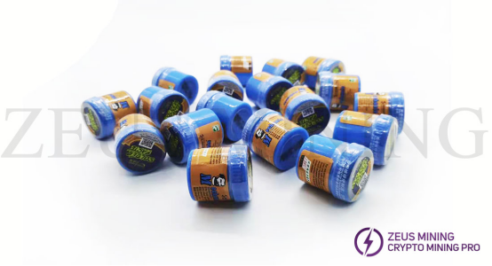
Solder balls are mainly caused by flying solder caused by rapid heating during the soldering process, and usually appear on the sides of chip components or between fine pitch pins. In addition to causing solder dislocation and edge collapse, solder balls are also related to solder paste viscosity, oxidation degree, solder particle thickness, and flux activity. Let's look at these factors' impact on SMT patches today!
1. Solder paste viscosity
For solder paste with a suitable viscosity effect, its adhesion will offset the effect of solvent emission during heating and prevent the solder paste from collapsing.
2. Degree of solder paste oxidation
After the solder paste is exposed to air, oxidation may occur on the surface of the solder paste particles. The oxide of solder paste is generally controlled at about 0.03%, and the maximum value does not exceed 0.15%. Experiments have shown that the occurrence rate of solder balls is proportional to the percentage of solder paste oxide.
3. Thickness of solder particles
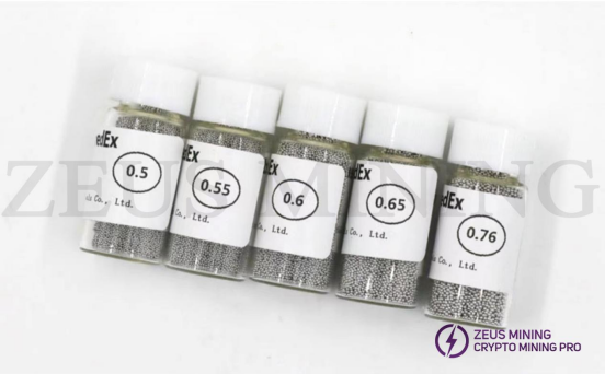
Suppose a large amount of particles below 20 μm is contained. In that case, the uniformity of the solder particles is not uniform. These particles have a large relative area, are very susceptible to oxidation, and are most likely to form solder balls. In addition, these tiny particles are also easily washed away from the pads during the evaporation of the solvent, increasing the chance of solder balls. Generally, the number of particles under 25um should not exceed 5% of the total number of solder particles.
4. Solder paste absorbs moisture
This situation can be divided into two categories: before using the solder paste, take it out of the refrigerator and open the lid immediately, causing water vapor to condense; insufficient drying before reflow soldering, residual solvent during solder heating makes the solvent and water boil and splash, Solder particles are sprayed onto the printed board to form solder balls. Depending on these two different situations, we can take the following two different actions:
1) Do not open the lid immediately after removing the solder paste from the refrigerator. Instead, it is recommended to return to room temperature and open the lid after it is stable.
2) Adjust the reflow soldering temperature curve so that the solder paste is fully preheated before soldering.
5. Flux activity
Solder balls are also prone to occur when the flux activity is low. The activity of uncleaned solder is generally slightly lower than that of rosin and water-soluble solder pastes. Therefore, pay attention to the formation of solder balls when using.


Comments
Post a Comment
Tell us your opinion