ASIC Miner ICERIVER KAS KS0 Profitability In the realm of cryptocurrency mining, the Iceriver KAS KS0 miner has garnered widespread attention. Tailored specifically for the Kaspa network's KHeavyHash algorithm, it boasts high hashing power and low power consumption, making it an ideal choice for many miners. In this article, we will comprehensively assess IceRiver KS0 profitability while considering the Kaspa market conditions and the attributes of KS0 miner. Kaspa Market Dynamics Kaspa is a vibrant cryptocurrency network aimed at delivering high performance and scalability for everyday transactions. At the time of writing this article, the Kaspa coin trades at approximately $0.04959. But it's essential to note that cryptocurrency markets are highly susceptible to price volatility. Hence, investors must remain vigilant about market dynamics. Additionally, the Kaspa network's mining difficulty and reward mechanisms play a role in mining returns. Attributes of the IceRiver KS...
How to repair the common faults of the Whatsminer M20S hash board?
This article will analyze the failure of the M20S hash board test log from the following aspects:
Fault 1: The number of reports of single-board test chips is incomplete
Test log phenomenon:
The test log shows that the RST signal of the hash board is normal, the temperature sensor is normal, and the SN code is normal, but the number of ASIC chips is not complete. Normally, 105 chips should be found, but only 73 chips were actually found.
Cause analysis:
"The number of single-board test chips is incomplete" indicates that the power supply unit of the Hash board is normal. Therefore, you can check the voltage of the RXD, TXD, and CLK signals and then find the faulty chip.
Check method:
1. Measure the RXD signal voltage (the RXD signal voltage is transmitted from the first chip to the last chip); its signal voltage usually is 1.8V. Generally, the investigation starts from the RXD signal of the first and last chip.
2. Measure the TXD signal voltage (the TXD signal voltage is transmitted from the last chip to the first chip); its signal voltage usually is 1.8V. Generally, the investigation starts from the TXD signal of the first and last chip.
3. Measure the CLK signal voltage (the CLK signal voltage is transmitted from the first chip to the last chip); the normal signal voltage is 0.9V. Generally, the investigation starts from the last chip corresponding to each group of CLK signals, finds the ASIC chip with abnormal signal voltage, and replaces it.
Fault 2: The single-board test chip reports 0
Test log phenomenon:
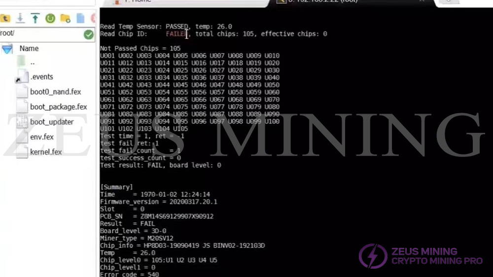
The test log shows that the hash board has a normal temperature sensor and SN code, but all ASIC chips have failed to be identified.
Cause analysis:
It is usually caused by the abnormality of the hash board's power supply unit or the ASIC signal's abnormal voltage.
Check method:
1. Check whether the voltage between layers is normal. If it is abnormal, check the output voltage of the power supply (this voltage is the working voltage of the ASIC chip), the boost output (this voltage is the power supply for the LDO input of the last 8 layers), and the RXD signal voltage conversion chip ( The chip converts the 3.3V voltage of the control board to the 1.8V voltage of the RXD signal).
2. If the interlayer voltage is normal, check the LDO 1.8V and 0.8V power supply, and the RST, CLK, RXD, and TXD signal voltages (RST, CLK, and RXD are all transmitted from UI to U105, and TXD is transmitted from U105 to U1).
Fault 3: The single-board test chip reports that the RST signal reset failed
Test log phenomenon:
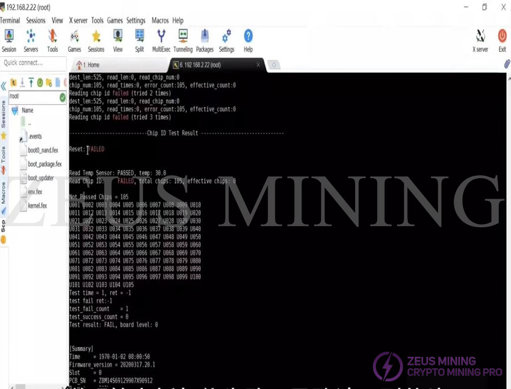
The test log shows that the hash board has a normal temperature sensor and SN code, but the failure of the RST signal to reset causes all ASIC chips to fail to be identified.
Cause analysis: (in two cases)
1. The reset fails, and the LED light is on
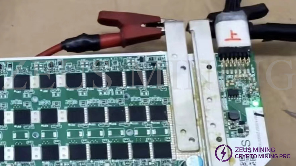
During the test, the positive and negative poles of the hash board are powered on, and the LED lights up. This is because the RST signal of the hash board outputs a high level of 1.8V, which drives the LED light to light up. Normally, the hash board RST is at a low level of 0V, and the light is off. Use the command " echo 0 > /sys/class/gpio/gpio99/value " to set the RST signal to a high level of 1.8V, from U1→U105 to find where RST has changed from a low level of 0V to a high level, and find the faulty chip.
2. The test reset fails, and the LED light does not light up.
This is because the RST signal is interrupted due to a problem in the transmission process of U1→U105 and cannot be transmitted. Use the command "echo 1 > /sys/class/gpio/gpio99/value" to set the RST signal to a high level of 1.8V, and from U1→U105 to find where RST has changed from a high level of 1.8V to a low level, find the faulty chip.
Check method:
Measure the RST signal voltage (the RST signal voltage is transmitted from the first chip to the last chip), generally start the investigation from the RST signal of the first and last chips, and find the ASIC chip with abnormal signal voltage and replace it.


Comments
Post a Comment
Tell us your opinion