ASIC Miner ICERIVER KAS KS0 Profitability In the realm of cryptocurrency mining, the Iceriver KAS KS0 miner has garnered widespread attention. Tailored specifically for the Kaspa network's KHeavyHash algorithm, it boasts high hashing power and low power consumption, making it an ideal choice for many miners. In this article, we will comprehensively assess IceRiver KS0 profitability while considering the Kaspa market conditions and the attributes of KS0 miner. Kaspa Market Dynamics Kaspa is a vibrant cryptocurrency network aimed at delivering high performance and scalability for everyday transactions. At the time of writing this article, the Kaspa coin trades at approximately $0.04959. But it's essential to note that cryptocurrency markets are highly susceptible to price volatility. Hence, investors must remain vigilant about market dynamics. Additionally, the Kaspa network's mining difficulty and reward mechanisms play a role in mining returns. Attributes of the IceRiver KS...
How to use the soldering iron and matters needing attention
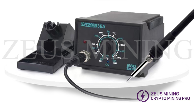
The electric soldering iron is a very simple and common tool for welding. It is very convenient to use. It can be used for electronic production and electrical maintenance welding wire components. So, how to use the soldering iron correctly? What should we pay attention to when using it? Through this article, let's find out together!
How to hold the soldering iron?
There are three main ways to hold the soldering iron:
① Reverse grip method, that is, use five fingers to hold the handle of the electric soldering iron in the palm. This method suits high-power electric soldering irons and welding workpieces with large heat dissipation.
② Positive grip method, hold the handle of the soldering iron with four fingers and press the thumb along the direction of the soldering iron. This method is suitable for larger electric soldering irons and is generally used for curved soldering iron tips.
③ Hold the pen method, that is, use the method of holding the pen to hold the electric soldering iron. This method is suitable for low-power electric soldering irons, welding parts with small heat dissipation, such as soldering printed circuit boards, and maintenance.
Precautions before using the soldering iron
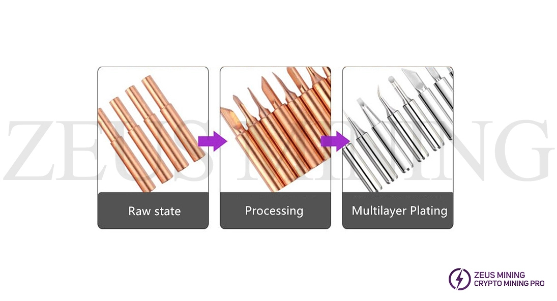
Power up the tip to "tin" the tip before use. You can choose a suitable iron tip according to the welding needs and connect the power supply. When the soldering iron tip temperature rises to the point where it can melt tin, dip the soldering iron tip on the rosin, and then apply a layer of solder after the rosin smokes; repeat this two or three times so that the blade surface of the soldering iron head can be used with a layer of tin.
The electric soldering iron should not be energized for a long time without using it. This will easily cause the soldering iron core to oxidize and burn out, shortening its life. At the same time, it will also cause the soldering iron tip to oxidize due to long-term heating and even be "burned" and no longer "eat tin."
How to use a soldering iron?
1. Select suitable solder and use low melting point solder wire or paste for soldering electronic components.
2. Flux, dissolve 25% rosin in 75% alcohol (weight ratio) as flux.
3. Before using the electric soldering iron, tin the iron head first. The specific operation method: heat the electric soldering iron. When the solder is just melted, apply flux, and then apply solder evenly on the tip of the soldering iron so that the tip eats a layer of the tin evenly.
4. Soldering method: Clean the pads and the pins of the components with fine sandpaper and apply flux. Then use the soldering iron tip to take an appropriate amount of solder to contact the solder joints. After all the solder on the solder joints has melted and immersed the component leads, the electric soldering iron tip is gently lifted along the pins of the components to leave the solder joints.
5. The welding time should not be too long; otherwise, the components will be easily scalded.
6. The solder joint should be in the shape of a sine wave, the surface should be bright and smooth, without tin thorns, and the amount of tin should be moderate.
7. After the soldering is completed, use an alcohol or circuit board cleaning solution to clean the residual flux on the circuit board to prevent the oxidized flux from affecting the circuit's normal operation.
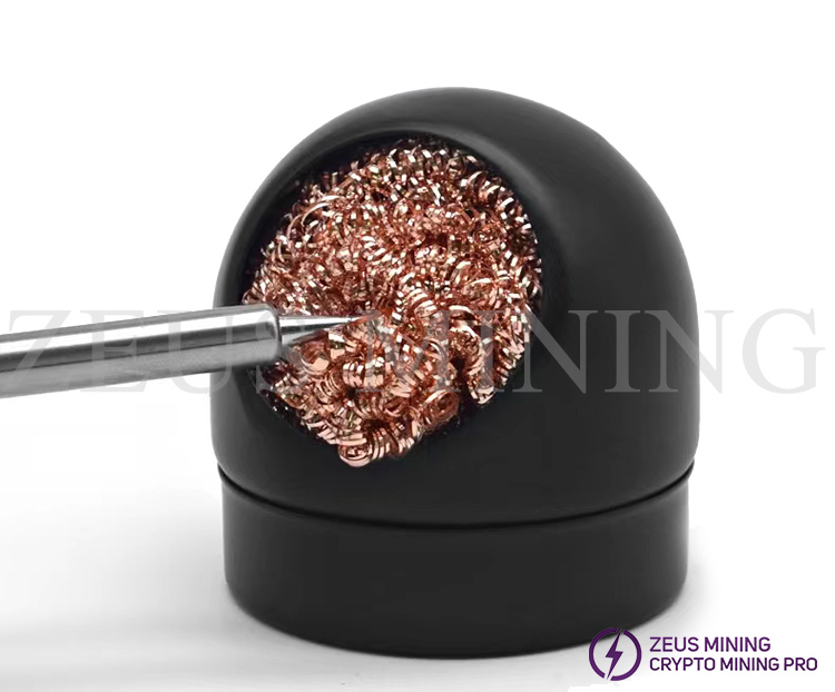
8. After use, the soldering iron should be placed on the soldering iron stand or in the tin cleaning ball to prevent the soldering iron tip from scalding the components.
Precautions for the use of electric soldering iron
1. Treatment of the new soldering iron before use. A new soldering iron cannot be used right away. It should be plated with a layer of solder before use.
The specific method is: to select a suitable soldering iron tip and connect the power supply. When the soldering iron tip temperature rises to melt tin, apply rosin to the soldering iron tip, and then apply a solder layer after the rosin smokes. Repeat three times; an oxide layer will be formed on the blade surface of the soldering iron head and its surroundings, which will cause the phenomenon of "eating tin" difficult. At this time, the oxide layer can be removed and re-plated with solder.
2. Adjust the length of the soldering iron tip. When soldering integrated circuits and transistors, the temperature of the soldering iron tip should not be too high, and the time should not be too long. At this time, the length of the soldering iron tip inserted into the soldering iron core can be adjusted appropriately, thereby controlling the temperature of the soldering iron tip.
3. There are two soldering iron tips: straight and elbow. When using the pen-holding method, the electric soldering iron with a straight soldering iron tip is more flexible to use. Suitable for soldering in circuits with many components. Using the positive grip method of the electric soldering iron with a curved soldering tip is more suitable. It is mostly used for soldering when the circuit board is vertical to the desktop.
4. If the electric soldering iron is not used after being energized for a long time, it is easy to accelerate the oxidation of the electric soldering iron core and burn out. At the same time, the soldering iron tip will be oxidized due to prolonged heating and even burn to "death" and no longer "eat tin."
5. Avoid misconnecting the lead wires when replacing the soldering iron core. For example, suppose the 220V AC power cord is connected to the terminal of the grounding wire by mistake. In that case, the shell of the electric soldering iron will be charged, and the welded parts will also be charged, which will cause an electric shock accident.
How to use a soldering iron?
Preheating: The tip of the soldering iron is at a 45-degree angle against the pad and the component feet. Preheat component pins and pads. The tip of the soldering iron tip should not stand against the copper-free position of the PCB board, which may burn the board into a trace; the soldering iron tip should preferably follow the direction of the line: the soldering iron tip should not plug the via hole: the preheating time is 1 to 2 seconds.
Tinning: Introduce the tin wire from the contact surface of the component foot and the soldering iron; when the tin wire is melted, master the wire feeding speed; when the tin is scattered over the entire pad, remove the tin wire; the tin wire should not be directly on the tip of the soldering iron, To prevent the flux from burning black; the entire tinning time is about 1 to 2 seconds.
Remove the tin wire: remove it and place it on the pad; the time is about 1 to 2 seconds.
Remove the soldering iron: Remove the soldering iron when only a slight smoke comes out of the solder: the solder joint is solidified.
Welding is very simple. If you use the correct method, pay more attention, and practice more, you can easily master the tricks.


Comments
Post a Comment
Tell us your opinion